01 Sep Blink on ESP32 WROVER Module using the E-Lagori Basic kit
Introduction: After learning about the importance of block diagrams when we start implementing or prototyping them, lot of times the results are not acceptable or sufficient to move on to the MVP development stage. Prototyping is difficult as not everything is breadboard friendly or even perf-board friendly, especially when the modules you want to use are in the form of SMD, QFP or BGA packages. Hence, E-Lagori allows you to prototype your idea or concept level block diagram into an industrial prototype at affordable costs with ease and simplicity, reducing prototyping costs and turnaround time.
Step1: Arduino Installation
Arduino can be installed directly from their official website: https://www.arduino.cc/en/software.
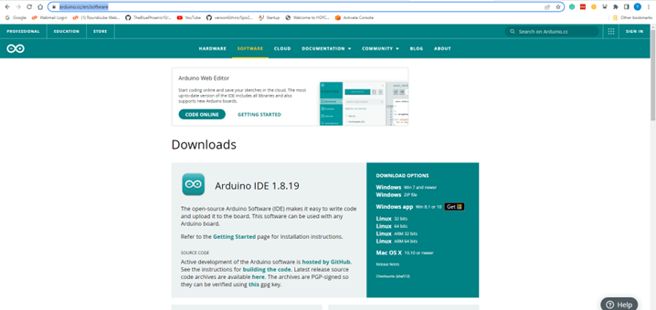
Select the suitable Operating System running on your PC and click just download.
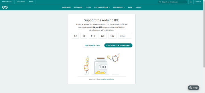
The download will start and an executable file will get downloaded. On windows, it will be a .exe file or it will directly install the app from MS Store for Windows 8.1 and above. For Linux, a tar or .xz file will be downloaded, which is a compressed format. For this guide, we will focus on the Windows installation path.
Once downloaded, click on the .exe executable and follow the instructions as shown in the video. The IDE (Integrated Development Environment) will get downloaded and make your life easier while coding.
Step 2: Adding ESP32 boards to Arduino
To add the ESP32 boards to Arduino, you can follow this guide: https://randomnerdtutorials.com/installing-the-esp32-board-in-arduino-ide-windows-instructions/. Go to File -> Preferences and enter the following to the “Additional Board Manager URLs” field: https://raw.githubusercontent.com/espressif/arduino-esp32/gh-pages/package_esp32_index.json
Subsequently, Go to Tools -> Board -> Boards Manager… and search for ESP32 by “Espressif Systems”.
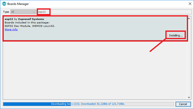
Once installed, select the Tools -> Board -> ESP32 Arduino -> ESP32 Wrover Module and leave the default settings as they are. It might look different in different systems as shown below.
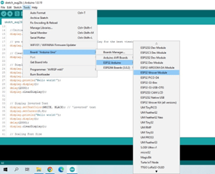
Then select the correct COM port leaving the remaining settings as they are.
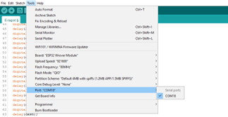
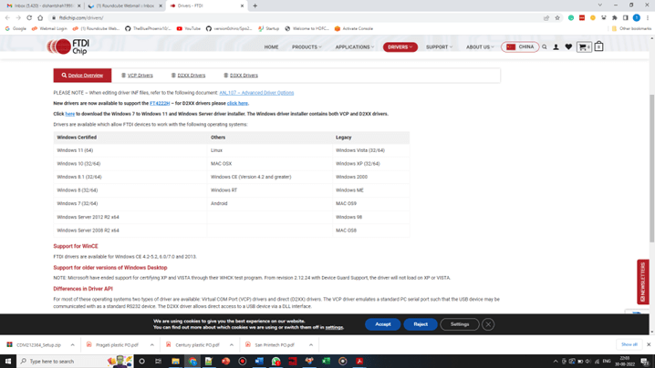
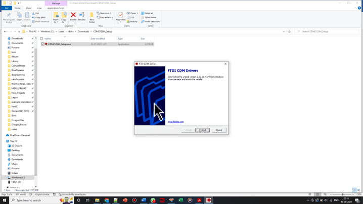
If you cannot find the com port, add the FTDI driver from this website: https://ftdichip.com/drivers/. A zip file containing the .exe file for installing the driver will get downloaded. Unzip the same using winrar or some other suitable decompressor and install the driver using the .exe file. Click Yes when the User Account control window pops up, to start the installer.
Click extract to complete the installation.
Restart Arduino and check for the Com port again.
Step 3: Adding E-Lagori ELi_McM_4_00 library.
Method A:
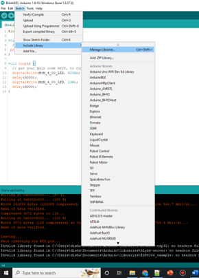
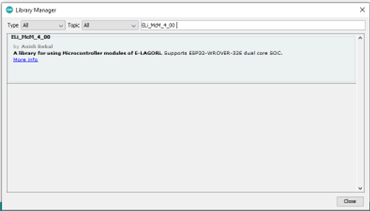
The best and easiest way to add the E-Lagori library for the ESP32-WROVER Processor board is to go to Sketch -> Include Library -> Manage Libraries… Then, paste ELi_McM_4_00 in the search bar and install the latest version available.
Method B:
The other method, which allows you to install the most recent version of the source that might not have yet been uploaded on Arduino can be to install the library from its github source: https://github.com/E-Lagori/ELi_McM_4_00. This might be a library version still under test hence install at your own risk and do not use it in a production version of a product.
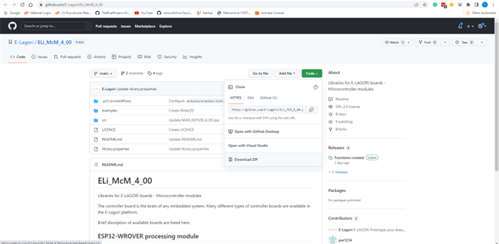
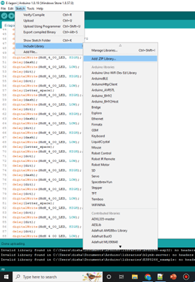
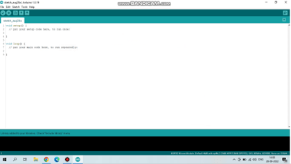
Download as Zip under “Code” and then install the zip file as a library in the Arduino IDE using Sketch -> Add .ZIP Library… and then select the zip file that was just downloaded. You should also receive a confirmation in the IDE’s cmd dump as shown below on successful addition of the library to Arduino.
Step 4: E-Lagori Board Assembly:
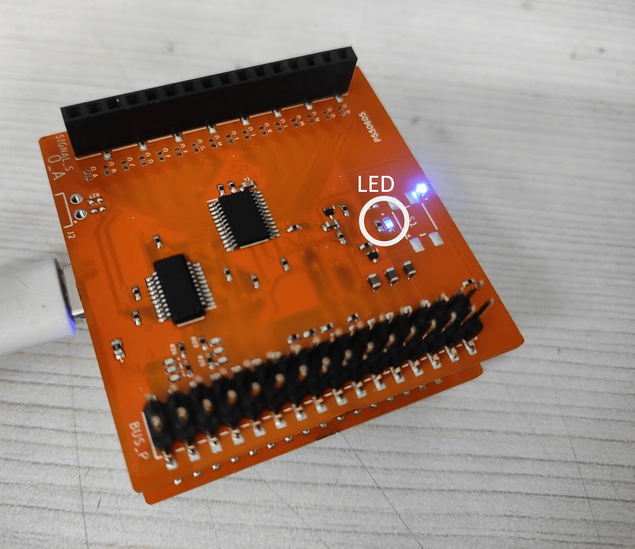
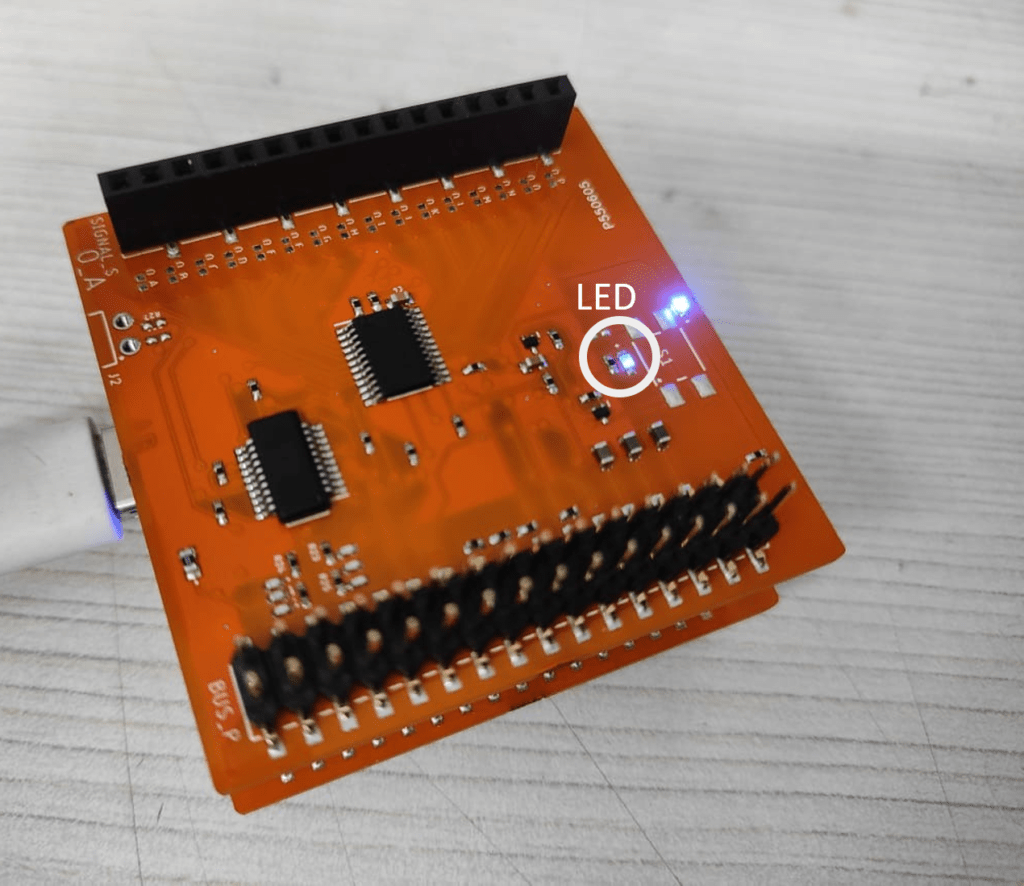
Connect the E-Lagori ESP32-WROVER Processor board to the USB C Type Power Supply board such that the ESP32-Wrover module and the USB-C connector face the inside. Keep the assembly such that the LED on the ESP32 board faces the top:
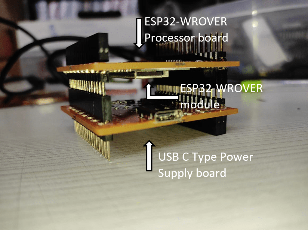
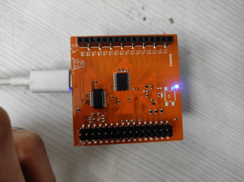
Connect the E-Lagori ESP32-WROVER Processor board to the USB C Type Power Supply board such that the ESP32-Wrover module and the USB-C connector face the inside. Keep the assembly such that the LED on the ESP32 board faces the top:
Step 5: Example Code Upload:
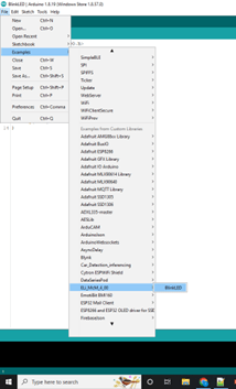
Finally, Go to File -> Examples -> ELi_McM_4_00 -> BlinkLED. The following example should open. Subsequently, press Ctrl+U or the arrow button as marked to upload the example code to the E-Lagori ESP32-WROVER Processor board.
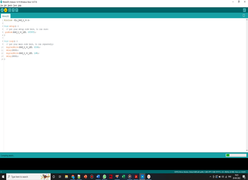
If all things go well, The LED under Switch SW1 of the module should Blink for 3 seconds! Congratulations on uploading your first code on the E-Lagori platform!

Menbehealth.Wordpress.Com
Posted at 19:35h, 26 MarchHi there, this weekend is good in favor of me,
sincde this point in time i am reading this great informative piece oof writing here at my home. https://menbehealth.Wordpress.com/
sprunki
Posted at 02:37h, 09 FebruaryWonderful article! If you're passionate about music, you'll love Sprunki Games - it's changing how we experience music.
נערות ליווי
Posted at 22:24h, 11 AprilI was very pleased to uncover this great site. I need to to thank you for ones time for this fantastic read!! I definitely appreciated every bit of it and I have you bookmarked to look at new information on your blog.
דירות דיסקרטיות בתל אביב
Posted at 14:24h, 07 AprilGreetings! Very helpful advice in this particular article! It is the little changes that will make the most important changes. Thanks a lot for sharing!