27 Sep Sensor fusion of 8 PT1000 temperature sensors
– By Raghurama BL, Prajwal Nataraj, Dr. Anish Bekal
Introduction
With rising complexity of systems there is an increasing need for array of temperatures to monitor various system parameters to prevent catastrophic failures or to optimize the outputs. The temperature sensor arrays are used in various applications such as battery temperature monitoring, Solar panel monitoring, vertical farming, boilers and furnaces etc. In all these applications accurate temperature with large range is essential. They also require high reliability and hence temperature sensors such as PT100, PT1000 or thermocouples are used.

For temperature sensing we typically need a wheatstone bridge for converting resistance into voltage. As well known, wheatstone bridge has a four resistors which under balanced condition gives a difference voltage of zero volts between the arms of the bridge.
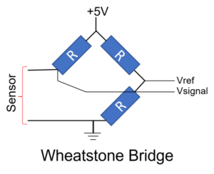
System Design
For building such systems lets make a block diagram for temperature sensor system that we need to build.
Individual sensor block diagram

The block diagram consists of PT1000 which will be the temperature sensor to be used in the system connected to a bridge where differential voltage is generated. The generated differential voltage is converted into a single ended voltage using an Instrumentation amplifier. The output of the amplifier is accepted as input by an Analog to Digital converter which provides a digitized output to a processor where temperature is calculated. The calculated temperature is transferred to a mobile app via blue tooth interface.
Block diagram of multisensor system

Several of the sensor system as described in the previous configuration can be connected to phone app. This configuration is very popular in distributed architectures like home heating etc. However, if we need to take readings from co-located sensors then an alternate configuration can be explored.
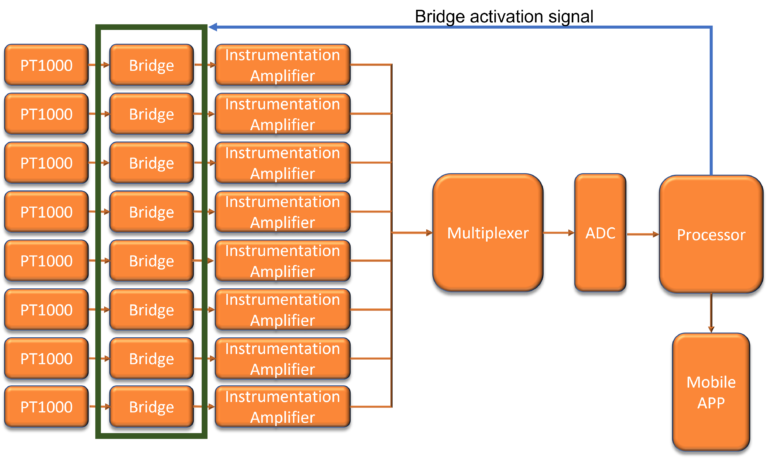
Multiple PT1000 temperature sensors can be connected to individual instrumentation amplifier module and an analog multiplexer can be used to select the signal into a single ADC. A single microcontroller/microprocessor can acquire the data in multiplexed manner and send it to a mobile app after processing. Bridge can also be switched off when not in use using a control signal from the processor
Ordering modules from E-Lagori website (www.e-lagori.com)
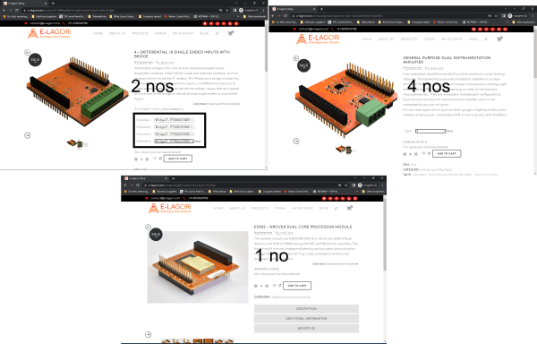
Order following components from E-LAGORi website.
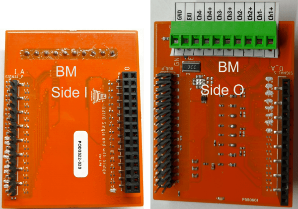
2 nos of 4 – Differential/8 Single ended inputs with bridge ( one module has 4 quarter bridge circuits)
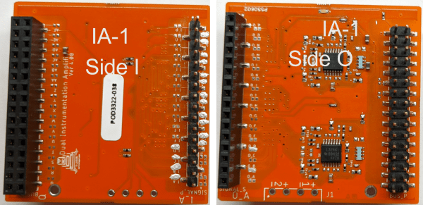
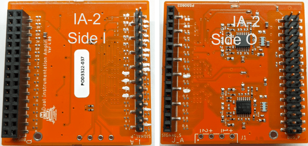
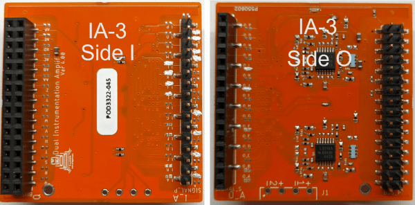
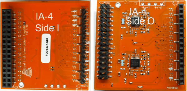
4 nos of General purpose instrumentation amplifier (Gain 3) (one module has 2 Instrumentation amplifier)
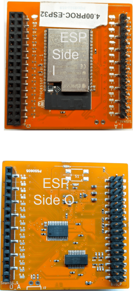
1 no of ESP32-WROVER dual core processor module
Good waterproof PT1000 sensors are available from Yog electroprocess pvt ltd.
Assembly of modules as per block diagram
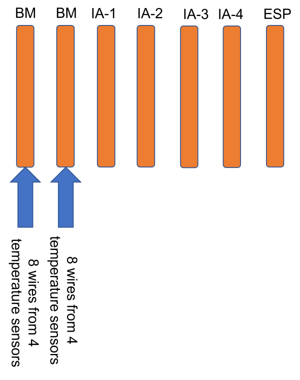
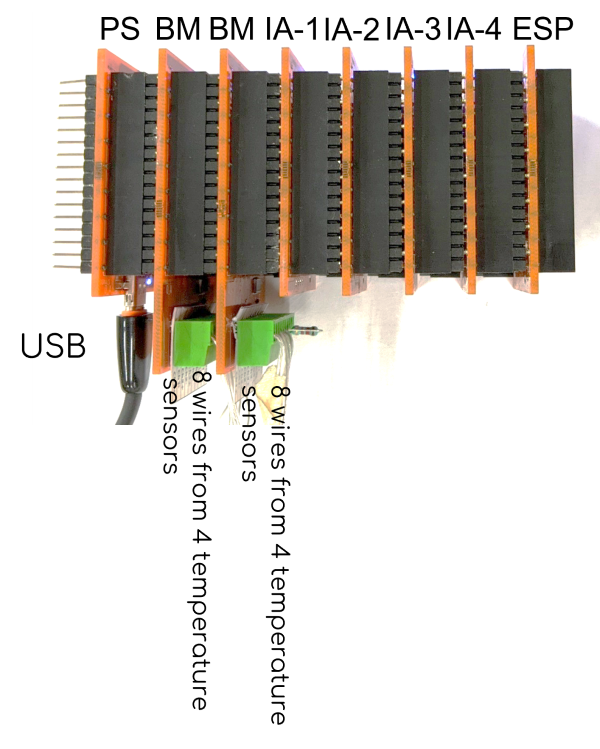
The modules need to be arranged in the same sequence as the block diagram without attaching them physically. Next connections have to be identified and made before connecting them
Connecting jumpers on the E-Lagori board
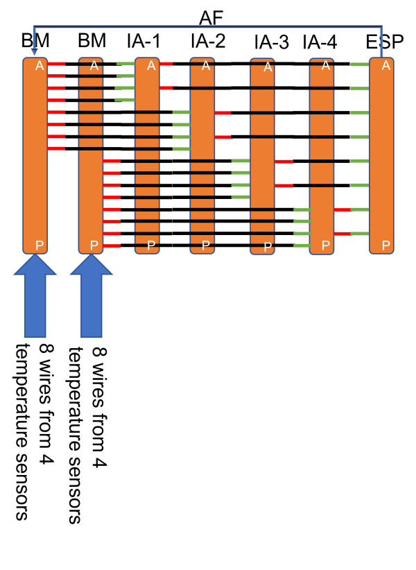
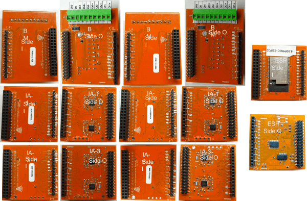
Green lines represent input jumpers, Red lines represent output jumpers and black lines represent the bypass jumpers.
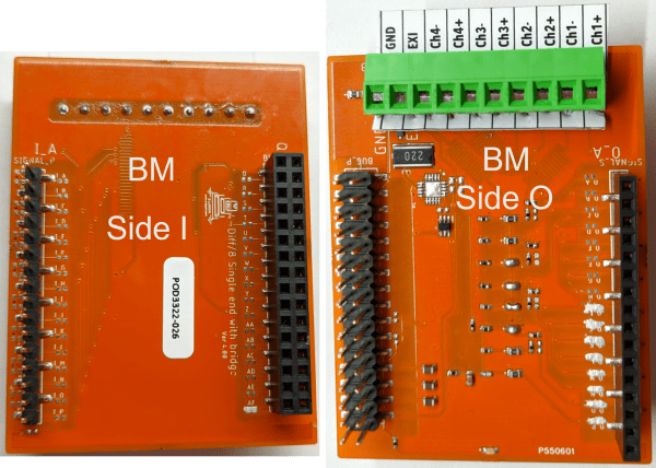
In summary, the 4 no’s of PT1000 sensors are connected to each Bridge board and the outputs are routed to jumpers (O_I, O_J), (O_K, O_L) , (O_M, O_N) , (O_O, O_P). These outputs are differential in nature. In the second board outputs are routed to (O_A, O_B), (O_C, O_D), (O_E, O_F), (O_G, O_H). The signals from the previous board are bypassed by shorting I, J, K, L, M, N bypass jumpers. Each Instrumentation amplifier can process 2 differential signals. So (O_A, O_B), (O_C, O_D) will be taken in first IA-1 by shorting jumpers (I_A, I_B), (I_C, I_D). The outputs are routed to O_B and O_D. Other signals are bypassed further. This is continued in all the IA boards hence processing 2 differential signals in each board. The output signals that are not being processed in the current board are bypassed by shorting the bypass jumpers. Finally all the outputs will be available in O_B, O_D, O_F, O_H, O_J, O_L, O_N, O_P. These are taken into the ESP32 processor board by shorting the I_B, I_D, I_F, I_H, I_J, I_L, I_N, I_P jumpers. The microprocessor will sample this through the mux.
MEasurement setup
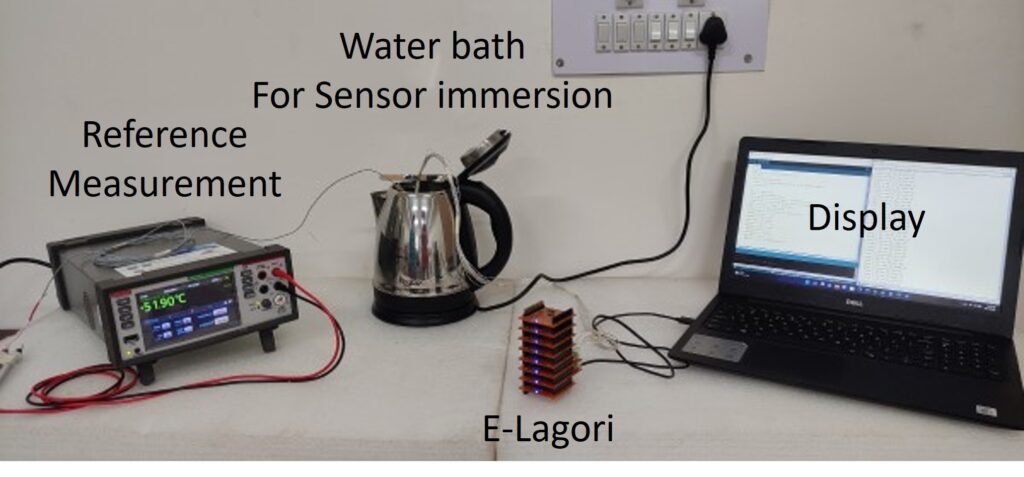
Our test setup consists of ELAGORi boards stacked up in the order as previously mentioned, a commercial temperature sensor display of reference temperature. A PT 100 is used as reference sensor is immersed in water inside a heater flask. The PT1000 temperature sensor which are 8 in number is also immersed in the same water heater. The USB of the E-LAGORi board is connected to a laptop with arduino ide and serial plotter is used to view the temperatures measured by the PT1000 sensors through the E-LAGORi boards
Results
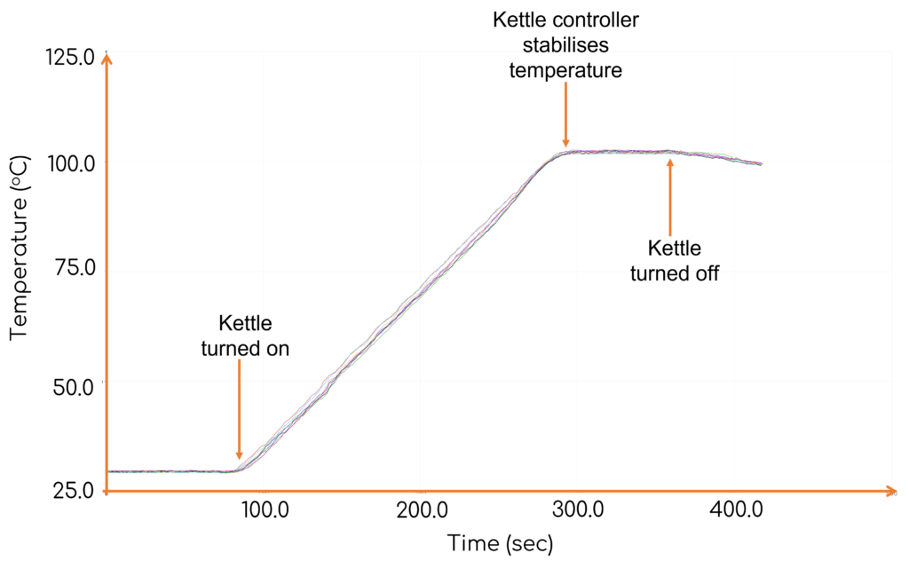
All the eight PT1000 RTD and one PT100 reference RTD are placed inside the kettle filled with water. The water temperature was measured as 29 degC by both reference RTD and the RTD array. At about 100 seconds, kettle is turned on and the kettle temperature steadily raises to 100 degC in 200 seconds. At 300 secs, the kettle stabilizes the temperature at 100 degC. All RTD temperatures are similar. The kettle is turned off at 350 seconds and the temperature of the water begins to drop. The entire physical process is recorded with good accuracy using our 8 RTD array.
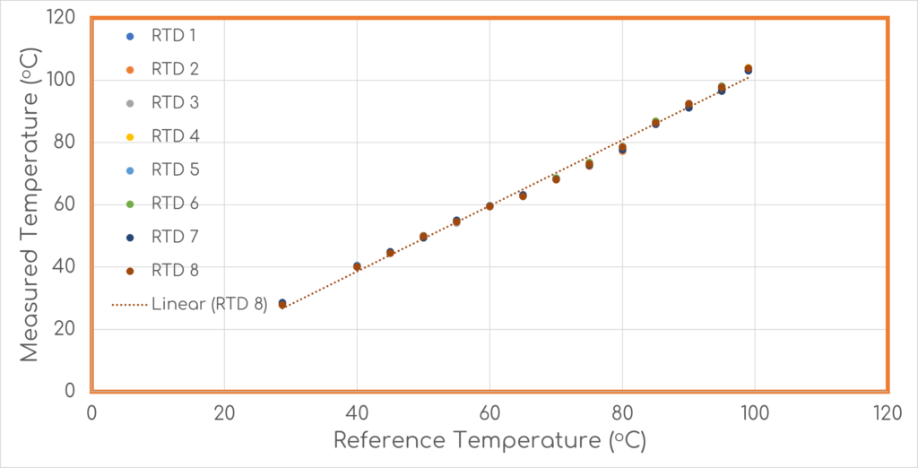
A comparison with reference RTD and E-LAGORI RTD array is performed and is as shown in the figure below. The sensor reading from all 8 RTD’s are almost identical and they overlap on each other. The measurement shows reasonable accuracy with respect to the reference RTD and the error is about +/-2 deg only at high temperatures which may be because of the bubbling as the RTD array and the reference RTD are not co-located.
Conclusion
Thus we can see that a RTD array can be easily constructed using E-LAGORi boards in about 30 minuites. Data can be sent to a mobile phone using bluetooth protocol.
In the next blog we will interface a few soil moisture conductivity sensor to the same stack.
Do comment and let us know whether you liked this blog and also watch the youtube channel to see the construction and demonstration of this experiment.
Visit E-LAGORi github page to download the code (https://github.com/E-Lagori/Applications/tree/main/RTDarray).
Appendix - Jumper shorts

Chloet
Posted at 05:40h, 25 JanuaryCan provide a link mass to your website https://zetds.seychellesyoga.com/info
Katherinet
Posted at 00:11h, 25 JanuaryWeb Development Wizards https://zetds.seychellesyoga.com/info
Bridgett
Posted at 17:45h, 24 JanuaryContent for your website https://zetds.seychellesyoga.com/info
נערות ליווי
Posted at 22:25h, 11 AprilI was very pleased to uncover this great site. I need to to thank you for ones time for this fantastic read!! I definitely appreciated every bit of it and I have you bookmarked to look at new information on your blog.
דירות דיסקרטיות בתל אביב
Posted at 14:24h, 07 AprilGreetings! Very helpful advice in this particular article! It is the little changes that will make the most important changes. Thanks a lot for sharing!